Nidhish_Jain-s_BSE_Portfolio
This is a template portfolio for the students attending the BlueStamp Engineering program.
Robot that uses Computer Vision to track a ball
This will serve as a brief description of your project. Limit this to three sentences because it can become overly long at that point. This copy should draw the user in and make she/him want to read more.
| Engineer | School | Area of Interest | Grade |
|---|---|---|---|
| Nidhish J. | Dalton School | Machine Learning | Incoming Senior |
Demo Video
#Future Steps
In addition to completing the project, I would also like to attempt to use a convolutional neural network (CNN) to detect a ball. The main advantaged of using a CNN to detect a ball over color detection, is that the CNN can detect a ball through the RPi Camera regaurdless of its color. It can do this because the main objective of a CNN is to find patterns based on pixel values. When using a CNN
#Third Milestone
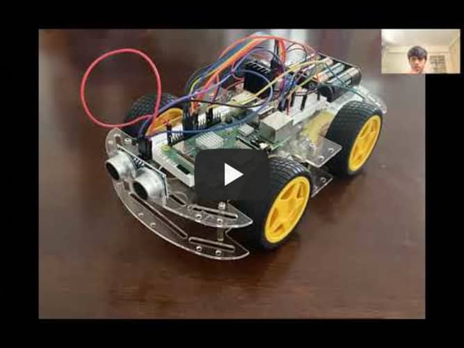
For my third milestone, my plan was to interface the motors of the smart car chassis with the color detection portion of my OpenCV code, in order for the car to follow a tennis ball. Unfortunately, the motors of the car broke down so I was not able to complete the final step of this project. If I am able to obtain new motors in the future, I would love to complete it and demo the car following a tennis ball in real time. Nevertheless, here is the code that would enable the car to follow a tennis ball.
Second Milestone
After I got the smart car to move, I decided to write the code for color detection using OpenCV. After connecting the RPi Camera to the Rasberry Pi unit, I imported the open CV packages on the terminal. My first step was to create trackbars that determined the color that the camera was looking for. Since color is based on the parameters of RGB, I made three trackbars for each color: red, green, and blue. The values that determine the intensity of the color range from 0-255, so as I scroll the trackbar up, I can increase the intensity of each color, to match the color that I would like to detect.
First Milestone
My first milestone was to set up the smart car chassis, make it move, and make it stop based on ultrasonic sensor input. After sautering the wire connections to the motors and the battery, I assembled the chassis. The chassis consisted of two acryllic plates, acryllic fasteners, and standoffs. I used the fasteners to attch the motors to one plate, and then screwed in the standoffs to mount the second plate on top of the first. Afterwards, I connected the jumper wires from the motors to the terminals on the LN298 motor driver.In order to turn, go forward, and backward, I coupled the motors vertically, so that the wheels on the left side worked as one unit, and the wheels on the right side as another. In addition, I connected the positive wire from an external battery to the 12V terminal on the motor driver, and the negative wire from the battery to the ground terminal. Finally,to connect the motor driver to the Rasberry Pi, I plugged in 6 jumper wires on the input pins of the driver, and pligged them into the GPIO pins on the Rasberry Pi. For a firrst pass setting up and hooking up the Raspberry Pi and all the necessary components onto my tv. The heatsinks, the sd card, and the controller were all added to ensure that the Raspberry Pi was working. Instead of the Raspberry Pi Os software, I had to first download a different software called Retro Pie. With Retro Pie, I needed to download an Imager for Raspberry Pi. Raspberry Pi Imager automatically downloads a list of the latest versions of Raspbian supported by the Raspberry Pi. Raspbian is the typical Raspberry Pi Os software, the one I needed on the Raspberry Pi was Retro Pi. With the included SD card, I plugged in the SD into my computer and launched the Imager. The imager allowed me to set the Operating System to Retro Pi instead of Raspbian onto the SD card. With the OS imaged onto the SD, I plugged the SD card back into the Raspberry Pi and rebooted the system and Retro Bi booted up.
